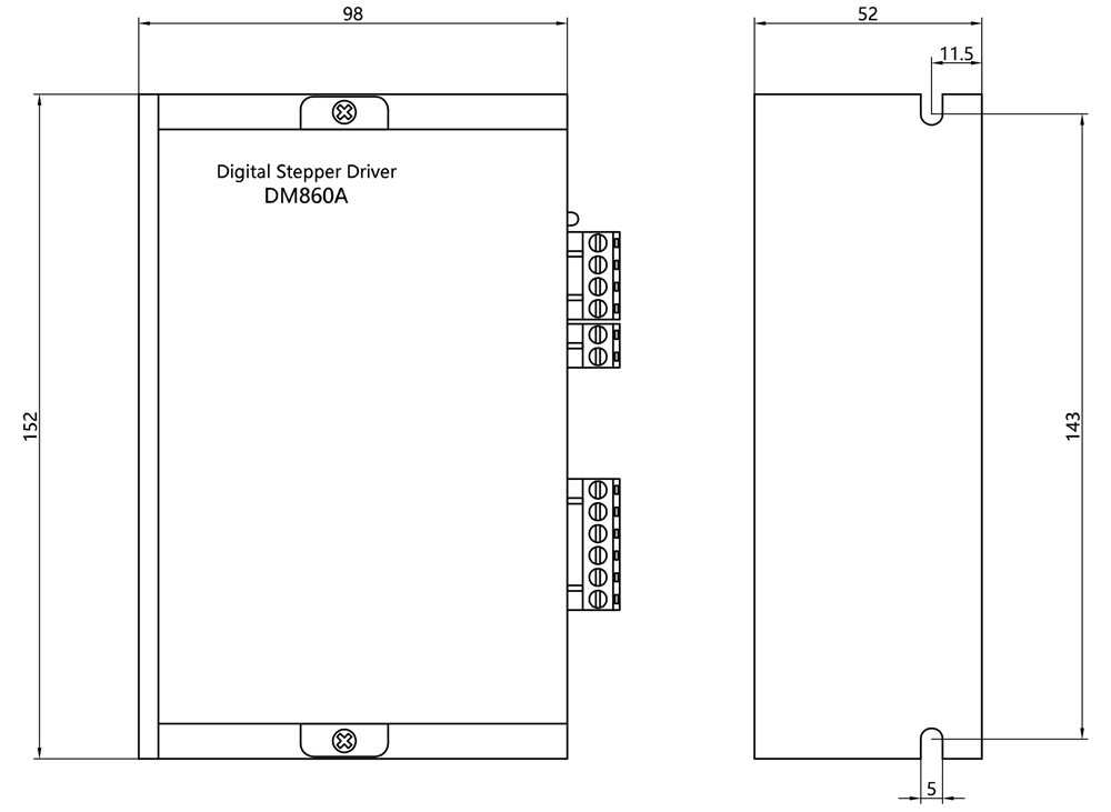
Our DM860A is a high-performance digital stepper driver based on DSP and PID control algorithm with microstep control technology. The stepper motors driven by DM860A can run with much smaller noise and much less vibration than other drivers in the market. The DM860A possess the feature of lower noise, lower vibration, and lower heating. Its voltage is AC20V~80V. It is suitable for all the 2-phase hybrid stepper motor whose current is less than 7.2A. There are 16 kinds of microstep of DM860A. The maximum step number of DM860A is 51200 steps/rev (microstep is 1/256 ). Its current range is 2.4A~7.2A, and its output current has 8 stalls. DM860A stepper driver has automatic semi-flow, over-voltage, under voltage and over-current protection function. Our DM860A stepper driver can be applied in a variety of small scale automation equipment and instruments, such as labeling machine, cutting machine, packing machine, drawing machine, engraving machine, CNC machine and so on.
1.Features
● Adoption of 32-bit DSP, pure sine wave subdivision technology
● Low-noise, low-vibration and low temperature rising(with fan)
● Voltage 36~110VDC or 24~80VAC
● With 8 stalls output current setting, peak current 7.2A
● With16 stalls microstep subdivision setting
● Automatic half current, self-test, over voltage, under voltage, over current protection
● Internal optical isolation, highest frequency response 200KHZ.
● Suitable for current range 2.4~7.2A 2-phase, 4-phase nema34 stepper motor
2.Microstep Resolution Selection
Pulse/REV |
SW5 |
SW6 |
SW7 |
SW8 |
Default |
ON |
ON |
ON |
ON |
800 |
OFF |
ON |
ON |
ON |
1600 |
ON |
OFF |
ON |
ON |
3200 |
OFF |
OFF |
ON |
ON |
6400 |
ON |
ON |
OFF |
ON |
12800 |
OFF |
ON |
OFF |
ON |
25600 |
ON |
OFF |
OFF |
ON |
51200 |
OFF |
OFF |
OFF |
ON |
1000 |
ON |
ON |
ON |
OFF |
2000 |
OFF |
ON |
ON |
OFF |
4000 |
ON |
OFF |
ON |
OFF |
5000 |
OFF |
OFF |
ON |
OFF |
8000 |
ON |
ON |
OFF |
OFF |
10000 |
OFF |
ON |
OFF |
OFF |
20000 |
ON |
OFF |
OFF |
OFF |
40000 |
OFF |
OFF |
OFF |
OFF |
Default: The pulse can be customized according to customers’ requirements.
3.Current Setting
REF |
Peak |
SW1 |
SW2 |
SW3 |
2.00A |
2.40A |
ON |
ON |
ON |
2.57A |
3.08A |
OFF |
ON |
ON |
3.14A |
3.77A |
ON |
OFF |
ON |
3.71A |
4.45A |
OFF |
OFF |
ON |
4.28A |
5.14A |
ON |
ON |
OFF |
4.86A |
5.83A |
OFF |
ON |
OFF |
5.43A |
6.52A |
ON |
OFF |
OFF |
6.00A |
7.20A |
OFF |
OFF |
OFF |
Users can set the driver half flow function by SW4. "OFF" indicates the quiescent current is set to half of the dynamic current. "ON" indicates the quiescent current and the dynamic current are the same. User can set SW4 to "OFF", in order to reduce motor and driver heating and improve reliability.
4.Interface description
Signal |
Function |
Operating Instructions |
ALARM/PWR |
Indicator Lights |
There are two indicator lights. Power indicator is green. When the stepper driver power on, the green light will always be lit. Fault indicator is red, when there is over-voltage or over-current fault, the red light will always be lit; after the driver fault is cleared, if re-power the red light will be off. |
DIR-/DIR+ |
Signal Interfaces |
PUL+ and PUL- are the positive and negative side of control pulse signal; DIR+ and DIR- are the positive and negative side of direction signal; ENA+ and ENA- are the positive and negative side of enable signal. |
PUL-/PUL+ | ||
ENA-/ENA+ | ||
A+ |
Motor Interfaces |
A+ and A- are connected to a phase winding of motor; B+ and B are connected to another phase winding of motor. If you need to backward, one of the phase windings can be reversed. |
A- | ||
B+ | ||
B- | ||
VCC |
Power Interfaces |
The stepper driver uses AC power supply. Recommended operating voltage is 20VAC-80VAC, and power consumption should be greater than 350W. |
VCC |
5.Overall Dimensions


Copyright © Changzhou Jinsanshi Mechatronics Co., Ltd. All rights reserved. - Privacy policy